Electromagnetic Induction – NCERT
Question 6.1
Predict the direction of induced current in the situations described by the following Figs. 6.15(a) to (f).
Basic Principle Used (Very Important)
Lenz’s Law:
The induced current is always in such a direction that it opposes the change in magnetic flux producing it.
So, for every diagram, we follow three steps:
-
Decide whether magnetic flux is increasing or decreasing
-
Decide how the loop will oppose this change
-
Use right-hand thumb rule to get current direction
Fig. 6.15 (a): North pole of magnet moving towards the coil
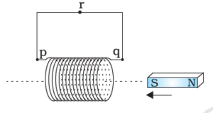
Analysis
-
Magnetic flux increases through the coil.
-
Coil must oppose increase in flux.
-
So, the face of the coil towards the magnet becomes North pole.
Direction of induced current
➡️ Anticlockwise (as seen from the magnet side)
Fig. 6.15 (b): North pole of magnet moving away from the coil
Analysis
-
Magnetic flux decreases.
-
Coil tries to oppose decrease in flux.
-
Coil face becomes South pole to attract the retreating magnet.
Direction of induced current
➡️ Clockwise (as seen from the magnet side)
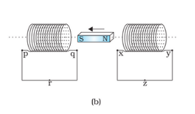
Fig. 6.15 (c): South pole of magnet moving towards the coil
Analysis
-
Magnetic flux increases.
-
Coil must oppose this increase.
-
Coil face becomes South pole (repels approaching south pole).
Direction of induced current
➡️ Clockwise (as seen from the magnet side)
Fig. 6.15 (d): South pole of magnet moving away from the coil
Analysis
-
Magnetic flux decreases.
-
Coil tries to maintain flux.
-
Coil face becomes North pole to attract the receding south pole.
Direction of induced current
➡️ Anticlockwise (as seen from the magnet side)
Fig. 6.15 (e): Coil moving towards a stationary magnet
Analysis
-
Relative motion causes increase in magnetic flux.
-
Situation is equivalent to magnet moving towards coil.
-
Coil must oppose increase in flux.
Direction of induced current
➡️ Same as Fig. 6.15(a)
➡️ Anticlockwise (from magnet side)
Fig. 6.15 (f): Coil moving away from a stationary magnet

Analysis
-
Magnetic flux decreases.
-
Coil tries to oppose decrease.
-
Equivalent to magnet moving away from coil.
Direction of induced current
➡️ Same as Fig. 6.15(b)
➡️ Clockwise (from magnet side)
Question 6.2
Use Lenz’s law to determine the direction of induced current in the situations described by Fig. 6.16:
(a) A wire of irregular shape turning into a circular shape
(b) A circular loop being deformed into a narrow straight wire
(Assume a uniform magnetic field perpendicular to the plane of the loop, as shown in the figure.)
Basic Idea (Must write in exam)
According to Lenz’s law,
The induced current always flows in such a direction that it opposes the change in magnetic flux causing it.
Magnetic flux:
So here, only area (A) is changing.
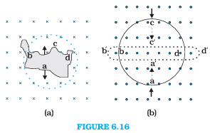
(a) Irregular wire turning into a circular loop
Analysis
-
For a given length of wire, a circle encloses the maximum area.
-
When the irregular loop becomes circular:
-
Area increases
-
Hence, magnetic flux increases
-
Application of Lenz’s law
-
The induced current must oppose the increase in flux.
-
Therefore, the loop produces a magnetic field opposite to the original field.
Direction of induced current
-
If the external magnetic field is into the plane of the paper (×):
-
Induced magnetic field must be out of the plane
-
By right-hand thumb rule → anticlockwise current
-
Answer (a): Induced current is anticlockwise
(b) Circular loop deformed into a narrow straight wire
Analysis
-
Deforming a circular loop into a straight wire:
-
Area decreases
-
Hence, magnetic flux decreases
-
Application of Lenz’s law
-
The induced current must oppose the decrease in flux.
-
So, it tries to maintain the original magnetic field direction.
Direction of induced current
-
If the original magnetic field is into the plane of the paper:
-
Induced field must also be into the plane
-
By right-hand thumb rule → clockwise current
-
Answer (b): Induced current is clockwise
Question 6.3
A long solenoid with 15 turns per cm has a small loop of area
2.0 cm² placed inside the solenoid normal to its axis.
If the current carried by the solenoid changes steadily from 2.0 A to 4.0 A in 0.1 s, find the induced emf in the loop while the current is changing.
Given Data
-
Turns per unit length of solenoid:
-
Area of small loop:
-
Initial current:
-
Final current:
-
Time interval:
-
Permeability of free space:
Step 1: Magnetic field inside the solenoid
For a long solenoid,
Since current is changing,
Step 2: Rate of change of current
Step 3: Induced emf in the loop
Magnetic flux through the loop:
Induced emf:
Substitute values:
Step 4: Calculation
Final Answer
Question 6.4
A rectangular wire loop of sides 8 cm and 2 cm with a small cut is moving out of a region of uniform magnetic field of magnitude 0.3 T, directed normal to the loop. The velocity of the loop is 1 cm s⁻¹ in a direction normal to
(a) the longer side
(b) the shorter side
Find
(i) the emf developed across the cut, and
(ii) for how long the induced voltage lasts in each case.
Given Data
-
Magnetic field:
-
Velocity of loop:
-
Length of longer side:
-
Length of shorter side:
Basic Formula Used
When a loop moves out of a magnetic field,
(where is the length of the side cutting magnetic field lines)
(a) Velocity normal to the longer side
Induced emf
Here, the longer side (8 cm) cuts the magnetic field.
Time for which emf lasts
The emf exists while the loop is leaving the field region.
Distance to be covered = shorter side = 2 cm
(b) Velocity normal to the shorter side
Induced emf
Now, the shorter side (2 cm) cuts the magnetic field.
Time for which emf lasts
Distance to be covered = longer side = 8 cm
Question 6.5
A 1.0 m long metallic rod is rotated with an angular frequency of
400 rad s⁻¹ about an axis normal to the rod passing through its one end. The other end of the rod is in contact with a circular metallic ring. A uniform magnetic field of 0.5 T, parallel to the axis, exists everywhere. Calculate the emf developed between the centre and the ring.
Given Data
-
Length of rod:
-
Angular frequency:
-
Magnetic field:
Concept Used: Motional emf in a rotating rod
For a rod rotating in a uniform magnetic field, the emf developed between the centre and the rim is:
(This result comes from integrating the motional emf with .)
Calculation
Question 6.6
A horizontal straight wire of length 10 m, extending from east to west, is falling with a speed of 5.0 m s⁻¹, at right angles to the horizontal component of the Earth’s magnetic field,
Answer the following:
(a) What is the instantaneous value of the emf induced in the wire?
(b) What is the direction of the emf?
(c) Which end of the wire is at the higher electrical potential?
Given Data
-
Length of wire:
-
Speed of falling wire:
-
Horizontal magnetic field:
(a) Instantaneous value of induced emf
For a straight conductor moving perpendicular to a magnetic field,
Substitute values:
(b) Direction of the induced emf
-
Magnetic field is towards north (horizontal component of Earth’s field).
-
Wire is falling vertically downward.
-
Use Fleming’s right-hand rule (or Lorentz force rule):
-
First finger → Magnetic field (North)
-
Thumb → Velocity (Downward)
-
Middle finger → Induced emf/current
-
The induced emf is directed from West to East.
(c) Which end is at higher potential?
Since emf is directed from West to East:
-
East end is at higher potential
-
West end is at lower potential
Question 6.7
Current in a circuit falls from 5.0 A to 0.0 A in 0.1 s.
If an average induced emf of 200 V is produced, estimate the self-inductance of the circuit.
Given Data
Initial current:
Final current:
Time interval:
Average induced emf:
Formula Used
For self-induction,
Calculation
Question 6.8
A pair of adjacent coils has a mutual inductance of 1.5 H.
If the current in one coil changes from 0 to 20 A in 0.5 s, find the change of flux linkage with the other coil.
Given Data
-
Mutual inductance:
-
Initial current:
-
Final current:
Formula Used
Change in flux linkage is given by:
Calculation